Construction
Description
20 gauge sheet metal (thickness of 0.0359”) will be used in the construction of this containment apparatus. This will allow us to bend the sheet of metal in a Cornice brake to get the three-sided structure we will need. There is also a need for lips on the two open sides of the containment apparatus. This will allow us to attach the removable side panel with screws for access to the heat exchanging elements. Next, we will make a second sheet that is the size of the missing side and proceed to drill and tap holes into both the containment apparatus and the removable side panel.
Next, there will be two side panels with a 6” duct that will be applied to the open ends of the apparatus. This will be connected directly to the ducting via ducting that will end at the 6” fan motor (Figure 6), which will be installed directly to the unit. We will be able to attach piece to the containment apparatus with tapped holes.
After this has been completed, we will be able to install the heat exchanger. We will be placing the heat exchanger within the containment apparatus. This will allow for insulation as well as noise prevention within the unit. Next, we will be cutting holes within the removable side panel to accommodate the inlet and outlet tubes for the heat exchanger. The tubes will have to be drained and disconnected from the transport sections of tubing to fit into the containment apparatus, but after initial installation, there will not be a need to access the inner workings of the air handler. This allows for more of a semi-permanent installation of the heat exchanging coils.
Manufacturing issues
There may be issues with using the equipment here at CWU regarding the size of the air handling unit, namely using the Cornice Brake for the bending. If this is not a viable option, there will have to be sections cut from the raw stock of appropriate size with weldments to assemble the final product. There will have to be two cuts performed on the sheet metal, one for trimming and another for the removable side panel section. These cuts may be able to be performed on the plasma cutter, given that there will be an adequate support structure to hold up the overhanging material.
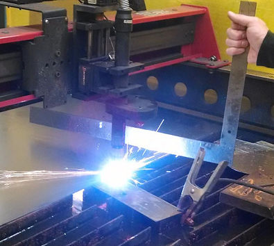
The first issue we encountered was the warping of the sheet metal during cutting with the plasma cutter, as seen below. Initially, this caused the head of the plasma cutter to become dislodged and stop cutting. We were able to put compression on said sheet metal and mitigate the warping, allowing for a clean, even cut.
Warping of sheet metal during cutting
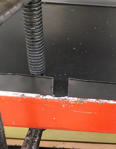
The next issue we encountered was that the given dimensions of the heat exchanger did not take into account some of the tubes coming out of the manifold, as seen in figure 8. This problem affected the containment apparatus as well as the removable side panel. Fabrication modifications were made, resulting in the appropriate fit of the heat exchanger into the assembled device (see figure 9).
Misconstrued dimensions of heat exchanger manifold
Corrected construction for heat exchanger manifold